6

Thanks to the loudness war, most modern music productions suffer from bad audio quality, distortion and clipping.

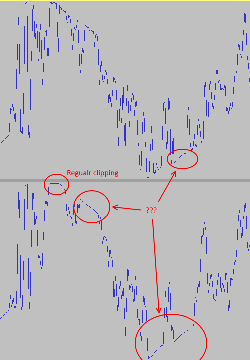
However, recently I noticed that some audio productions suffer from something I would call "diagonal clipping". This kind of clipping doesn't make sense to me, it doesn't help to make the recording louder.

See this picture I took from a pop song released in 2002:

diagonal clipping

Can anyone explain what went wrong here, or what purpose this "diagonal clipping" serves? First, I thought this was an issue with my ripping process, but then I downloaded the exact same song from YouTube (vevo), and the exact same patterns showed up.

4
  • 3
    Are you certain that's not an inherent VLF sine wave, showing through in gaps where no significant higher frequency is sounding?
    – Tetsujin
    Commented Jul 29, 2016 at 17:25
  • 1
    on the one hand i think tetsujin has a point , on the other hand , how do you expect from someone to answer if you dont provide the song, seriously in a full song i can understand 1000 more things listening to it rather than looking at the waveform... The best way to understand certain things about sound, is to follow the engineers that did it and the trail of the song... Was this analog / digital , where was it mastered, who did the job. You have to follow the trail of a song to see inside it. Other than that Tetsujins explanation could be the case..
    – frcake
    Commented Jul 29, 2016 at 17:45
  • Song is this one: youtube.com/watch?v=Cwkej79U3ek And here you can read about the recording: en.wikipedia.org/wiki/…
    – manuel
    Commented Jul 29, 2016 at 18:38
  • I don't think that this is a naturally occurring sine wave. The composition of smooth sine waves should always lead to a smooth graph as well. But here you can see sharp edges. Mathematicians would call this "non-differentiable". However, sine waves and a combination of sine waves are always differentiable.
    – manuel
    Commented Jul 29, 2016 at 18:43

3 Answers 3

9

This is just a limited (or clipped through distortion) sound wave added through the normal mixing process, to a lower frequency soundwave.

I've created a simple example to demonstrate what I mean.

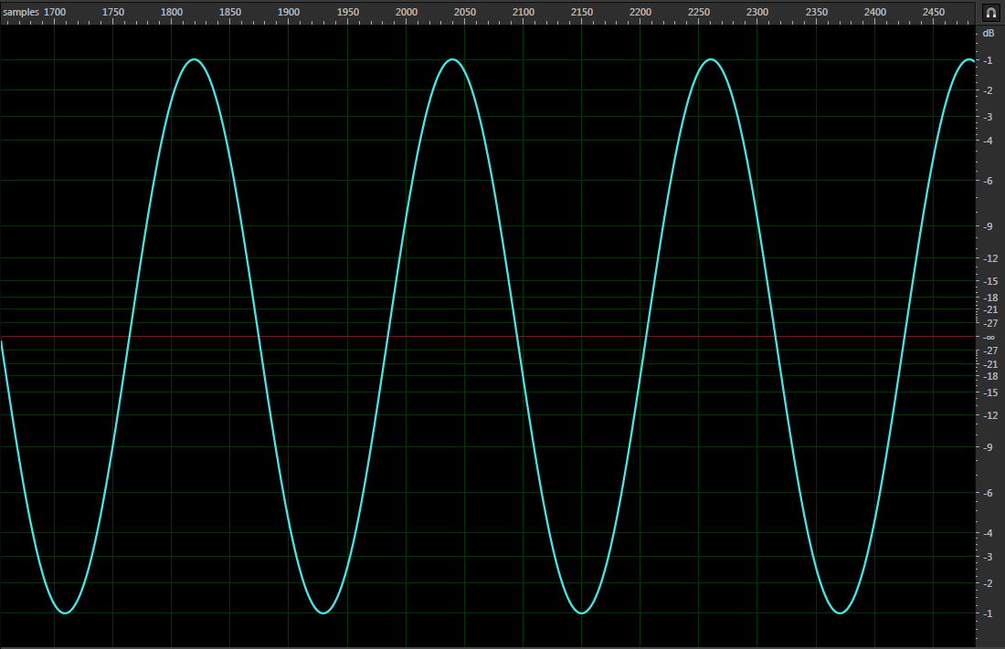
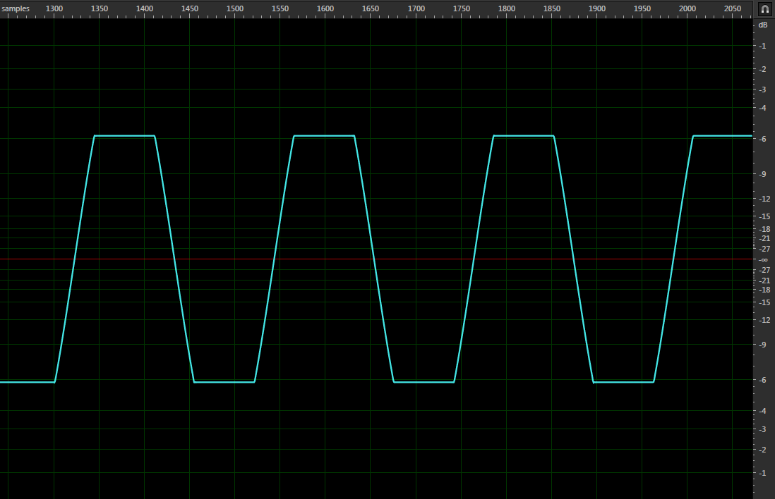
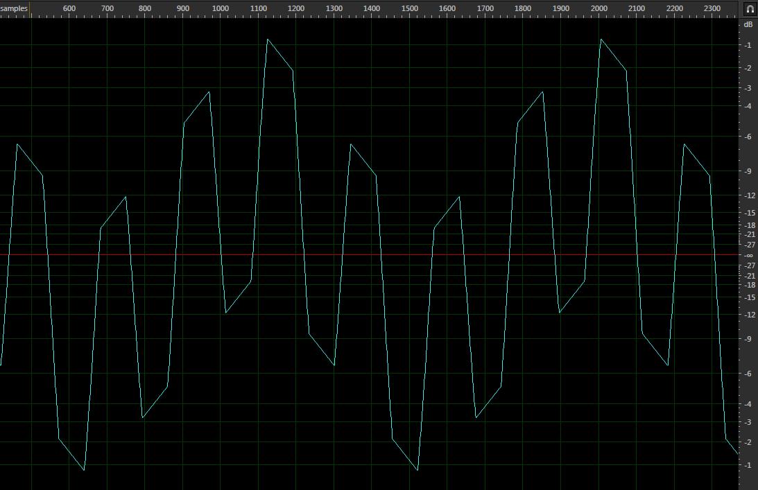
The higher frequency sound wave; Let's pretend it's a nice brass instrument: enter image description here The brass instrument is then clipped for whatever reason: enter image description here The clipped brass instrument is then added to the rest of the mix, which contains a triangular-like bass waveform.(I used a triangle-wave in this example because the example in the OP seems triangular-like): enter image description here

The adding of these waveforms results in the higher frequency waveform following the curve of the lower frequency waveform. This means that the flat-tops produced by the clipping will also follow the curve of the lower frequency waveform resulting in this seemingly "diagonal clipping".

4

You will note that this emulates the effect of a DC blocking capacitor, in a record player on clipped vinyl... i.e. no 0Hz being passed. This waveform's clipping slopes exclusively the same way, towards zero. Unless this were a mixture of a triangle, and a square (clipped) wave, of the same frequency, with a phase difference of 90 degrees, Marc W's example isn't what is being shown here.

The reason for this waveform: the producer has utilised a clipped sound, then the mastering engineer has opted to utilise a high pass filter... So the clipped section cannot maintain 0Hz at the noise ceiling, it decays back towards zero.

Though lowering the RMS by approx 2-3dB (you can in fact re-clip after a HPF, without the source suffering much more) this technique does appear to make the material mildly less fatiguing for the listener. As although your brain will still detect the harmonics of hard clipping, your ear drums are perhaps not having their mechanical limits emulated by the sound.

Edit:

With regards to the images that we've been presented with: firstly, we only have two cycles to make our assumptions from... I believe I'm probably looking at two examples of a clipped snare, immediately after the transient, with a HPF applied, post-clipping.

I encourage anyone to try this out.

Things that dissuade me from this precise assessment: nothing.

Regards to your answer, Marc: if we look at your resultant waveform, you show a squared-off waveform, (with a higher frequency than the triangle) superimposed upon the triangle. It bares very little resemblance to the image we're shown.

The very specific problem with your answer is that we are shown that the clipping occurs only at the crest and trough of both cycles that we see... We do not see what you illustrate (clipped peaks internally, in both directions).

[Another problem: the highs are being notably stuttered by the clipping. This would only really be acceptable around a transient, not in amongst a sustained bass sound... certainly for a 'pop song' anyway, rather than some aggressive dance music. Why would a 'sound professional' decide to clip a transient, with a large LF component displacement, then mix a triangle of the same frequency with it? I am baffled, this is surely how you illustrate incompetent mixing practices?!]

So... I tried my 'best' to give your explanation some credence: the two sources would have to be of the SAME frequency, and the clipped waveform would HAVE TO BE advanced by 90 degrees.

Problematically, we don't see a sharp enough drop in the centre of both images, in order for my modification of your assessment to work... but the wavefront appears to behave in the correct manner, as it approaches the first crest, in both images.

So, I could continue to mull over your suggestion Marc, and say: this could be a heavily clipped, extremely noisy sawtooth, added 90 degrees out of phase to a triangle.

There we go... Considerably more convoluted than my answer and very likely to be incorrect. Wouldn't you agree, Marc?

So. Finally, here is my full answer: The producer likely used a snare or kick sample, that was already clipped (or, because the two example images are slightly different, perhaps he/she utilised a hard clipper on their drum buss).

The mastering engineer applied a HPF, and limited/re-clipped... Hence, the tiny amount of 'regular clipping' illustrated.

4
  • I completely disagree with this, Your answer makes no sense from a sound professional's perspective. My theory demonstrates the exact results of the OP's image(although simplified). If what you describe is happening, then why does this 'HPF line' folow the lower frequency waveform's zero line exactly? If I had more time, I could reproduce the OP's waveform pretty closely using the most basic mixing techniques. P.S. "... a mixture of a triangle, and a square (clipped) wave, of the same frequency, with a phase difference of 90 degrees..."- This is completely wrong and not what I demonstrated!
    – n00dles
    Commented Aug 7, 2016 at 6:09
  • I think you took my answer too literally, but anyway; Your edit is more detailed and understandable, and I tend to agree with some of your assessment, but not all. Some things you say don't make sense and I would love to see your theory being practically demonstrated. I did try quickly, (without my usual equipment) but I got a different result. I'm not going to rattle off the problems I see with your answer, I'm going to +1 though, because it now seems more plausible although I still don't agree with it for this situation. I may try it again when I have time.
    – n00dles
    Commented Aug 8, 2016 at 16:31
  • You need to utilise a HPF at as low a frequency as possible. It needs to be subtle. Commented Aug 8, 2016 at 16:37
  • If you have any vinyl drum samples, from distorted '60s/'70s records... Have a zoom in. Unless it has been re-clipped, you will see exactly what the images show. Your original specific point of contention was my analysis of how your suggestion could create what we see. Adding your suggested waveforms, in my suggested manner, creates close to what we see. Try it. It would be a bizarre thing to do... but it's close. Commented Aug 8, 2016 at 16:46
0

Resurrecting an old thread but ill tell you from a perspective of a mastering engineer, the people responsible for the final quality control of frequency balance and loudness of music.

This is nothing but a pretty common technique to maintain snap on drums and other parts which are clipped to get the RMS level up of the signal.

After you clip a signal in the digital domain, you can pass it through tube based gear and overdrive it very little which would produce even order harmonics and convert the digital clips into what you all are calling ‘diagonal clipping’ , as you can see the diagonal begins from the left side and extends to the bottom, this would act as a transient for this signal and would help preserve attack. As you’re thinking that after clipping a signal why in the right mind would you pass it through another gear as it’ll result in peak overshoot and dissolve the effect of clipping. After passing a clipped signal through our gear we record it back to the PC and then soft clip this diagonal waveform to limit the peak overshoot.

You can easily replicate this effect in PC atop, just take a music file with drums and hard clip it until you see quite a few flat tops, then high pass it with a very narrow slope below 20hz, so that the low end is not messed up and voila you have this “diagonal clipping”

Whatever said by anyone here of mixing triangular sine and what not, do you think anyone would do all this triangle sine thing in the mastering process ? Where the goal is to be as transparent yet as impactful as possible ?

Your Answer

By clicking “Post Your Answer”, you agree to our terms of service and acknowledge you have read our privacy policy.

Not the answer you're looking for? Browse other questions tagged or ask your own question.